Saturday, July 20, 2013

Inter cell Interference Coordination

In LTE, due to orthogonal nature of OFDM signal, there is no intra cell interference. However, as the signal coming from different cells is not orthogonal in nature, cell edge user may experience interference from adjacent cell. LTE uses frequency reuse of one, meaning adjacent cells  may transmit on same frequency, resulting in inter-cell interference.

Inter-cell Interference Coordination (ICIC) is the method used in LTE to manage the interference arising due to signal coming from adjacent cell sites. The basic principle is to coordinate the scheduling of cell edge user in a way that users are not scheduled on same frequency time resources as users in other cell.

The coordination between cell sites is achieved by exchanging messages between eNodeBs over X2 interface. Two messages are defined for uplink interference coordination: High Interference Indicator (HII) and overload indication (OI).

High Interference Indicator HII) is used to communicate, on which frequency time resources and eNodeB is going to schedule cell edge users. By listening to this message, a neighbor eNodeB can avoid scheduling cell edge users in the indicated resources. This can, therefore, result in reduced uplink interference for both of the cells. The action to be taken by an eNodeB when it receives HII message is implementation specific.

An eNodeB send Overload Indicator message to indicate the level of interference experience in different frequency time resources to neighbor eNodeB. Three levels of interference are defined : Low, Mid and High. When an eNodeB receives overload indicator message, it can change the scheduling pattern to free the resources indicated in the overload indicator message, therefore, reducing the interference for cell edge users.

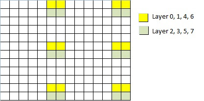
In the downlink, interference coordination can be achieved by controlling the downlink cell power for resources.  This is achieved by sending Relative Narrowband Transmit Power (RNTP) message. This message contains information whether or not the frequency time resource is limited by transmit power.  When a neighbor eNodeB listens to this message, it can avoid scheduling on the indicated resources. 

Thursday, July 4, 2013

Beam-forming in LTE

In LTE, various antenna technologies are used to provide better SNR. Transmit and receive diversity can be used to increase SNR by factor of number of transmit/receive antennas. Beam-forming can be used to provide better performance in low SNR and fading conditions.

Beam-forming involves shaping of the signal in the direction of the device. By applying appropriate precoding matrix, the strength of the signal can be increased in a particular direction. This is particularly useful for cell edge users.

The knowledge of the downlink channel is very essential for the eNodeB to apply appropriate precoding. In case of TDD, due the channel reciprocity, uplink channel quality estimation done by eNodeB can be used as estimation of downlink channel quality. In case of FDD however, that is not true. Beam-forming, is therefore, used particularly for TDD.

There are different ways to achieve beam-forming in different scenarios.. If the antenna signals are highly correlated, beam-forming can be achieved by applying different phase shifts to highly correlated signals. The signals are, therefore same, the only difference being phase shift. As the signals are highly correlated, this kind of beam-forming does not provide much protection against fading, it only provides better SNR.

If the antenna signal paths have low correlation, precoding matrix can be applied in such a way that precoded signal has both amplitude gain and phase difference. This kind of beam-forming provide much better results in faded channel conditions but it needs more detailed knowledge of the channel conditions.

Saturday, June 29, 2013

Transmission Mode 9


Transmission Mode 9 is new transmission mode defined in LTE release 10. It extends the concept of MIMO to 8 layers transmission. It support both SU-MIMO and MU-MIMO, it is possible to switch between two modes dynamically.

In order to support 8 layer transmission, LTE Release 10 extends the concept of downlink Demodulation Reference Symbols (DMRS) to 8 layers.  The precoding used for reference symbols is same as that used for PDSCH. Therefore, there is no need to explicitly signal precoding index.

The structure of DMRS for transmission mode 9 is shown in following figure:


To maintain the backward compatibility with Release 8/9, the structure for DMRS is similar to that used for transmission mode 7/8. DMRS for 8 layers is supported by having two different groups with lenght-4 Walsh–Hadamard orthogonal cover codes. In addition to DMRS, TM9 uses CSI reference symbols introduced in LTE release 10 for more effective estimation of CSI. 

To schedule data using transmission mode 9, a new DCI format 2C is introduced in LTE release 10. DCI 2C is based upon DCI format 2B, which is used for transmission mode 8. The number of layers can also be defined dynamically. The base station can schedule data on layers one to eight (antenna port 7 to 7+n).

The maximum number of codewords supported in transmission mode 9 is two even for eight antenna ports. This is same as maximum supported in different transmission mode in LTE release 8 and 9. The reason for this is, an increase in number of codewords would have resulted in increased signaling overhead. Various researches have proved that that increase in data rate by increasing number of codewords is very limited.

What are the benefits of using transmission mode 9.The answer to this question is, high cell edge data rates, better interference handling by base station, and therefore, improved coverage. TM9 can be combined with carrier aggregation and eICIC to create a highly spectrum efficient network.